|
I have never owned a "real" bench power supply, and frankly, I never had much use for it before. I'm used to just building whatever I need for a specific project.
I've always had more than a few standard psu's lying around, and I have a converted ATX-PSU with 3V3, 5V and 12V that is suitable for most basic projects, but I'm starting to understand why a good bench PSU is a nice thing to have.
Besides the obvious advantage of not having to spend time on finding a suitable PSU or building it, everytime I wanted to test something, I wanted to make a PSU with some nice extra features like current-limiting, dual output and logging/automation.
I didn't see any reason to reinvent the wheel, so to get me started, I build a dual version of GreatScott's Variable Lab Bench Power Supply
It's a relatively cheap and easy build that does most of the work, and since he does such a nice job explaining the process, I wont go into the details here.
To add the extra features, I had to switch the analog pots out with digital ones, and to do this I needed a rotary-potentiometer and a MCU to control them, this way I can also keep a log of voltage/current and use gnuplot to give me some nice graphics.
I bought a stack of MCP4131-104 100KOhm digital potentiometers and ended up with this monster, build in an old ATX-PSU kabinet:
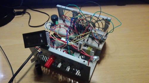 MCP4131 is basicly a stack of 128 resistors that can be switched digital, and after doing som testing, I discovered that it's not the most accurate component and since 100K is the maximum value (I need 500K), I instead ordered a couple of AD5242BRZ1M from Analog Devices, they are dual 1M and have a higher precision, unfortunatly they only come in SOIC16 package, so I guess it's about time I finished my micreoscope stand :-)
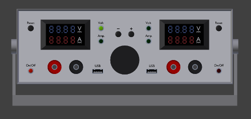
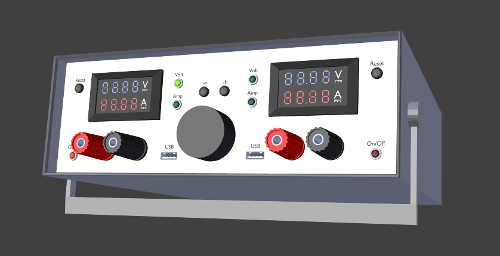
I designed a case for the final product in Blender, and with some help from Bill, I ended up with this:
I found the case on ebay (Hong Kong) so it'll most likely take a while to get here.
I ordered a couple of SOIC16 adapters to mount the AD5242BRZ1M on, but it can take up to 5 weeks for them to arrive, and since I'm eager to get on with the project, I made my own adapters out of stripboard, headers and some thin copperwire, and I'm actually quite pleased with the result:
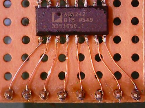
First I soldered 2 rows of headers and tied copperwire around them:
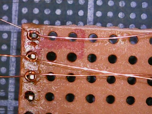
Then its just a matter of glueing the chip to the center of the stripboard, cut the wires in an suiatable length, find the smallest tip for the soldering iron and start soldering.
I bought a cheap 6£ USB microscope on ebay, and for things like this, it's perfect. btw... the two pictures above where taken with that microscope.
After playing around with the LTC3780 module, I concluded that it wassn't the best solution for my project, so now I'm building the whole thing from bottom up, it'll require some more work, but in the end I think I'll be better of. The LTC3780 module is still a nice a quick solution, but controlling it remotely is a bigger hassle than "just" making a whole new module.
Inspired by Peter Oakes briliant tutorial on youtube: Modular Bench Power System, I started building the Voltage-refference module using a Ref02 and an Op-Amp, and ordered parts for the output-driver.
Hopefully it'll all fit in the same case when I'm done :-)
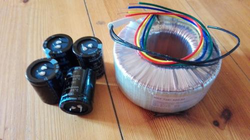
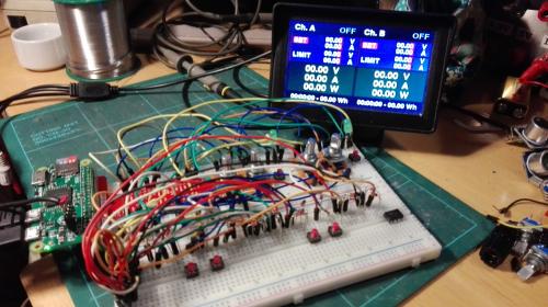
Finaly got my 2x30V/5A transformator and caps (nichicon) so now I can test it all together:
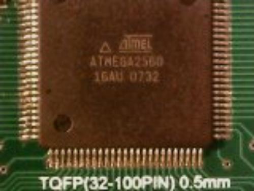
The biggest hurdle (since I haven't made a print yet) was the Atmega2560 and it's nasty 100pin TQFP socket, but I ended up with a decent result on a adapter-board, using a technique that Dave Jones call "drag-soldering":
The final pricetag will be around 1000,-Dkr (150,-USD), but concidering the specs, it's a bargain:
- 2X30V/5A constant current
- ±0.1% precision
- less than 2mA noise/ripple
- Linear
- Digital control
- 4" LCD
- USB and Ethernet
- 1 GHz ARM CPU (running Linux)
I thought about adding a constant current load, but decided to make it a sepperate unit.
The layout have changed a lot, and will most likely change even more in the final version, but this is its current form:
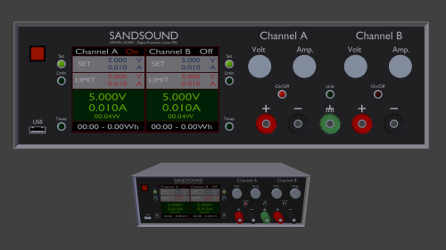
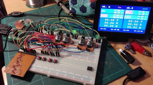
The interface uses a cheap 4" LCD connected to the composite out of a Raspberry Pi Zero, four rotary encoders and a bunch of buttons and LEDs. Right now it's just mounted on a breadboard:
The picture above doesn't do the screen justice, and it looks quite nice IRL.
The GUI is written in Python/Pygame, it's my first attempt at using Pygame, and thou I'm sure it can be done better, I'm quite pleased with the outcome.
I might port it to C++ sometime in the future, but for now, Python is a nice workflow.
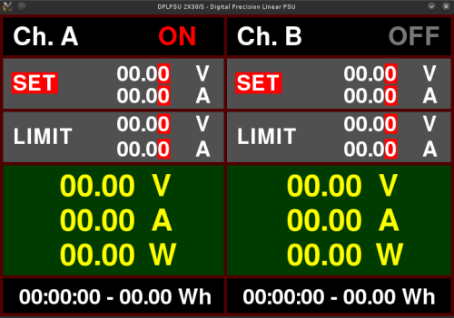
btw. the screenshot above is from my desktop, but on the Zero it runs without X, one of the major advanteges of using Pygame.
The Pi have several GPIO's but unfortunately not enough for my project, so I'm charlieplexing the buttons (the little matrix-board with all the diodes) to get 15 inputs on four GPIO's:
I ported the GUI to C++/SDL, and it runs real smooth. I haven't done any SDL since SabiCube (my sauerbraten mod), but it's not that different to Pygame. The entire program is only 34Kb and can be downloaded here:
PSU GUI C++/SDL cource code
Finally got everything in place on the frontpanel, only to find out that I hadn't accounted for cooling fans for the heatsinks inside the case... DOH...
So... another week, another case, and this time everything fits :-)
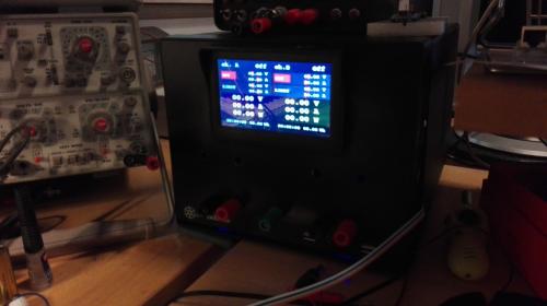
I found this IDX pc-case (SG13-Q) that was perfect for my project, so now I can begin asembling all the modules I've made, and once everything is tested together, I'll make a master-print for the frontpanel with all the buttons and encoders, and conectors for the V/A-sense and MCU modules. The power section will have it's own seperate print, but I still haven't found the best solution for the TO220 heatsinks.
|